
| Make / No. of Machines | Not Available |
|---|---|
| Model | Not Available |
| Title of the related experiment: | To produce a square hole/slot on a wood piece |
| A brief explanation of the usage of the said equipment | A stationary chain mortiser is a tool designed to cut square holes into a piece of wood, often to create mortise and tenon joints or post and beam fittings. Like other mortisers, the chain mortiser is designed to cut material squarely, which drill bits often cannot do. Unlike other mortisers, chain mortiser machines can quickly remove a significant amount of material, and the chain itself can be plunged deep into the wood to create deeper cuts. The chain runs around a bar, much like the design of a chainsaw, but usually on a smaller scale. The wood is placed on the machine's work surface and is usually clamped. A hand lever is provided on a drill press and used to drop the chain and bar to the piece of wood on the work surface. The machine may feature a depth gauge to control how deep the chain cuts. With this setup, students should be able to:
|
| Make / No. of Machines | International Machine Tool |
|---|---|
| Model | MT-D |
| Title of the related experiment: | Drilling for Pattern |
| A brief explanation of the usage of the said equipment | The universal movements of the tool head permit the drill tool to be located at any desired position over the stationary workpiece. The head contains an electric motor, V-pulleys and a V-belt that transmit rotary motion to the drill spindle at a number of speeds. The spindle is made of alloy steel. It rotates and moves up and down in a sleeve. A pinion engages a rack fixed onto the sleeve to provide vertical movement of the spindle, allowing the drill to be fed into or withdrawn from the workpiece while drilling. Spindle speed is changed with the help of V-belt and V-step-pulleys. With this setup, students should be able to:
|
| Make / No. of Machines | G. S. PAIK |
|---|---|
| Model | BS24 |
| Title of the related experiment: | The band saw machine for wood cutting in making patterns |
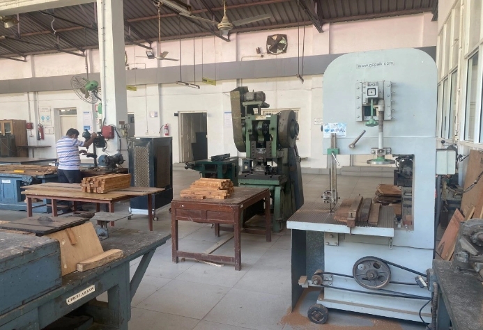
| A brief explanation of the usage of the said equipment | The band saw machine is used to perform wood-cutting operations in making patterns which are used in a casting process. In a bandsaw, workpieces are fed into the cutting edge of the machine. The bandsaw machine cuts by drawing a continuous metal band across the workpiece. The bandsaw blade is supported and driven by a drive wheel and an idler wheel. Because each tooth is a precision cutting tool, accuracy can be held to close tolerances. This eliminates or minimizes many secondary machining operations. In addition, chip removal is very fast. An electric motor drives a typical vertical bandsaw machine through a belt transmission. The belt allows adjustment of the blade speed. The blade rotates on a fixed track between the idler wheel mounted above the work table and the drive wheel mounted beneath the work table and cuts into the side of the stock. The stock is moved against the blade to cut. The table can be tilted front-to-back or sideways to allow the mitred cuts. With this setup, students should be able to:
|